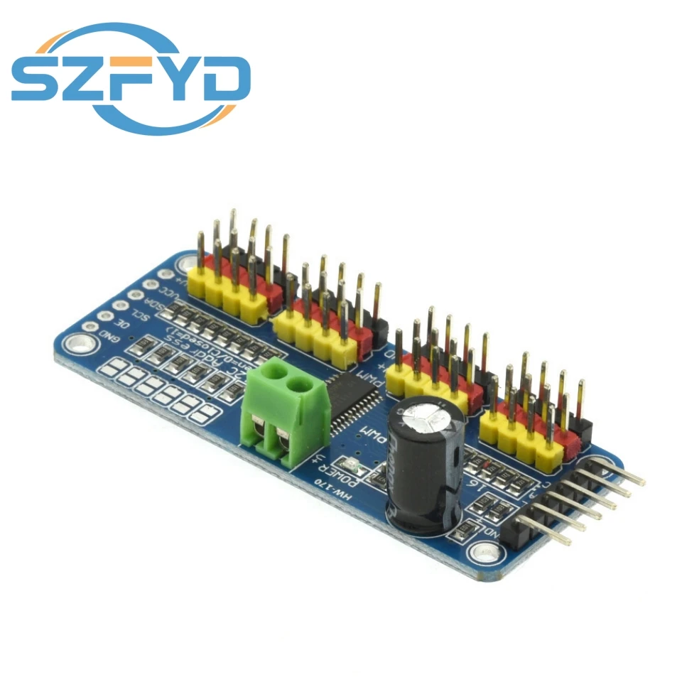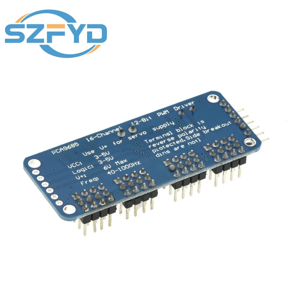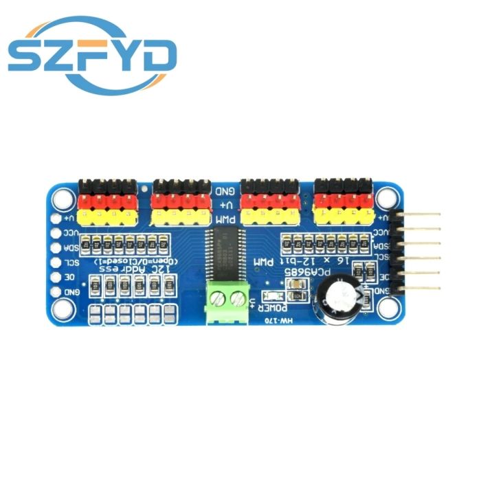
16 Channel 12-Bit PWM Servo Shield Driver I2C Interface PCA9685 Module For Raspberry Pi
Description:
100% brand new and high quality
Material: Electrical Components
Color: See pictures
Features:
You want to make a robot, When we saw this chip, we quickly realized what an excellent add-on this would be.
Using only two pins, control 16 free-running PWM outputs!
I2C input, control 16 PWM output, you can control the 16 way servo motor.
Specifications:
Frequency: 40-1000Hz.
Channel number: 16 channel.
Resolution: 12 bit.
Voltage: DC 5-10V
Size: 60*25mm/2.36"*0.98"
No retail package
Quantity:1Pc
Note: Due to the difference between different monitors, the picture may not reflect the actual color of the item. Thank you!!
(1)Drive board connected to Arduino:
The PWM driver board uses the I2C method, so only four lines can be connected to the Arduino device:
"Classic" Arduino pin mode:
+ 5v -> VCC
GND -> GND
Analog 4 -> SDA
Analog 5 -> SCL
Old Mega pin way:
+ 5v -> VCC
GND -> GND
Digital 20 -> SDA
Digital 21 -> SCL
R3 and later Arduino pin method (Uno, Mega &
Leonardo):
(These boards have dedicated SDA and SCL pins)
+ 5v -> VCC
GND -> GND
SDA -> SDA
SCL -> SCL
VCC pin is only for the chip power supply, if you want to connect the servo or LED lights, use the V + pin power supply, V + pin supports 3.3 ~ 6V power supply (chip safe voltage 5V). It is recommended to connect the external power supply via the power supply terminal.
(2) power supply part:
Most of the servo design voltage is 5 ~ 6V, especially in a number of steering gear at the same time running, with the need for high-power power supply. If you are directly using the Arduino 5V pin to power the servo directly, there are some unpredictable problems, so we recommend that you have a suitable external power supply for the drive board.
(3) Connect the servo:
Most servos are connected using standard 3-wire female plugs, as long as the corresponding pin into the driver board on it. (Ground wire is generally black or brown, the signal line is generally yellow or white)
(4) for the driver board assigned address:
Each drive board of the cascade needs to have a unique access address. The initial I2C address of each driver board is 0 × 40, you can modify the upper right corner of the jumper I2C address. Connect a jumper with solder to indicate a binary number "1".
Package includes:
1Pc x PCA9685 16-Channel 12-bit PWM Servo Motor Driver I2C Module For Arduino Robot